By Marc Venis B.A.Sc., M.A.Sc., P.Eng., President Vencon Technologies Inc.
For very special battery testing you might not want to use the built-in constant current load on the UBA.
The UBA is limited to discharging up to 2.5A per channel. This discharge rate is adequate for testing 99% of the batteries on the market. It is not sufficient to properly test batteries that are rapidly discharged in normal use (for example, some medical applications, UPS batteries and remote control aircraft and cars). For these batteries you should discharge them at a similar rate to the rate they get in normal use.
In other situations you might be fortunate to already have a constant current load that you would prefer to use. For instance, if you have a 10A logic controlled constant current load you could use your UBA to control it. This application note describes how to build and control an external discharger.
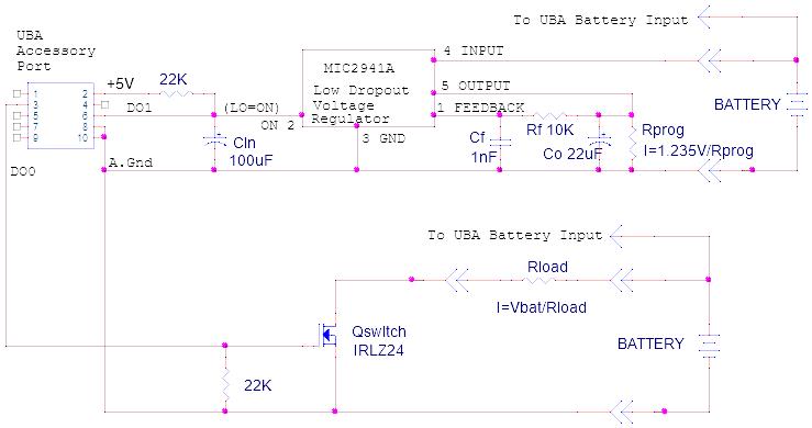
Schematic
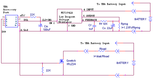
Circuit Description
This circuit contains two remotely controlled loads. The top part of the schematic is a regular off-the-shelf voltage regulator configured as a constant current load with on/off control. The bottom of the schematic is a MOSFET used to control a power resistor.
Inside your UBA, there is a 10 pin accessory header. On it are two programmable digital input/output lines which for controlling a remote load are configured as outputs. Pin 3 is digital output #0, pin 6 is digital output #1, pin 1 is digital ground, and pins 8 and 10 are analog ground. The accessory header is accessible by either removing the top cover of your UBA or by using an extension connector on the back of your UBA (preferred).
Caution The digital lines on the accessory port go directly to the digital output IC on the UBA. There is no extra static protection. You must take full static protection precautions when handling the connections and when designing the circuit. Your warranty does not cover any damage caused by static or mistakes in connecting to the accessory connector.
After power up digital control line 0 is high and line 1 is low. You can select the active state of the digital signal (see Setup). These digital lines can source and sink up to 2mA. Since there are two digital lines you can build up to two loads.
The circuit shown here contains two independent circuits for discharging. We built this circuit to test external load discharging, normally you wouldn’t build both circuits together.
Controlled Constant Current Load
The constant current load operates by supplying a fixed voltage to a resistor, Rprog. The load current is thus Vo/Rprog, where Vo is the output of the regulator, 1.235V for the MIC2941A part that we used. This circuit isn’t very practical since the output current is limited by the current limits of the regulator (usually around 1A) and all the power is dissipated in the regulator. Thus if you want to be able to test an eight cell battery your maximum current is limited to about 500mA with the regulator heat sinked. Since the UBA can discharge up to 2.5A there isn’t any advantage with this circuit. In addition, this circuit can only discharge down to about 2V, thus it can’t test a single cell (NiCd or NiMH). Instead of the voltage regulator used here you would probably use a commercial high power constant current load, or build your own to really take advantage of this technique.
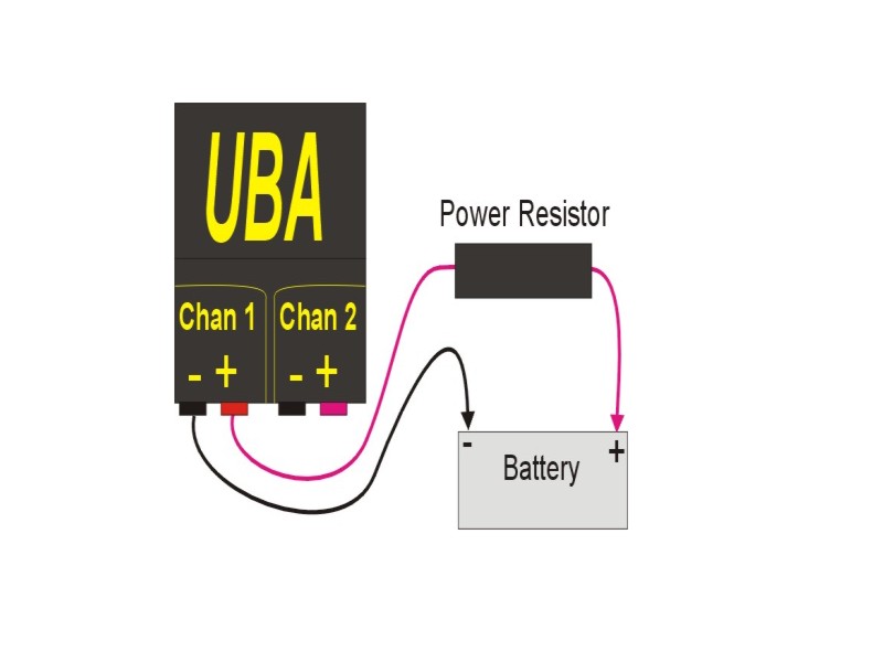
Switched Load
The bottom part of the schematic is a switch load. This circuit uses a power resistor for the load (Rload in the schematic). This circuit is simpler than the constant current load. Ideally you would use a precision power resistor for the load. Thus the discharge power is dissipated in a resistor, which is simpler to work with than an active device. For the high power load that we sell, we use a circuit similar to this to control the load which is a bank of light bulbs. Light bulbs have the advantage that they are inexpensive and somewhat constant current over their voltage range. Thus, as the battery voltage drops the current doesn’t drop as quickly as if using a resistive load.
This circuit requires that the resistance of the load be accurately known. This isn’t easy when the load resistors heat up and change their resistance. This is even more difficult when using lamps for the load as their resistance is non-linear (changing with voltage). For resistor loads the higher the wattage and the lower the tolerance the better. You should be using a resistor with a wattage of at least four times the power you intend to dissipate in it and with a tolerance of no more than 2%. For the high power load which we sell we provide a circuit which measures the current and feeds it to the UBA which uses this information to calculate battery capacity.
Another advantage of the resistive load is that it has no minimum voltage. The current doesn’t suddenly drop off below a certain voltage. Thus a resistive load is ideal for testing single cells.
Setup
In order to use your external loads you need to add these lines to your calibration file describing the load: For the Constant Current Load:
*ExtLoadDevice: name model aichan limit control Iin0 Vout0
ExtLoadDevice: My600mA_CC 2 -3 1 My600mA_SW 0.618 0
*ExtLoadControl: name model dochan maxamps
ExtLoadControl!: My600mA_SW 2 0x ! 1
For the Switched Resistor Load:
*ExtLoadDevice: name model resistor limit control
ExtLoadDevice: My10R 3 10 20 MySwitch
*ExtLoadControl: name model dochan maxamps
ExtLoadControl!: MySwitch 2 x1 ! 2
The lines starting with an asterisk (*) are comments.
The “ExtLoadDevice” & “ExtLoadControl” lines describe the constant current load (top half of schematic). Even though the constant current load is a single device, it is described by two lines.
The “ExtLoadDevice” line is for the constant current load. The model is ‘2’ which means that it is a constant current load. The analog input channel is ‘-1’, which means not used. The current limit is 1A. The load is controlled by the external load control “CCSwtich”. The “0.618 0” means that the load current is a constant 0.618A.
The “ExtLoadControl” line says that we are using an External Load Control. The first number, model number of 2 means that it is an on/off switch. The second item is 0x, which means that we are using the digital output 1 and it’s turned on by a low signal (digital output is specified in the form …cba where a is digital output “0” and can be “1” for high signal to turn load on, “0” for low signal, or “x” for not used and Similarly “b” is for digital output 1). The “!” means that the complement of the dochan is used to shut the load off. The last number is the maximum current that this switch can handle. In our case, 1 Amp.
The next set of “ExtLoadDevice” & “ExtLoadControl” lines describe the switched resistor load (bottom half of schematic). The external load device is the resistor and the external load control the FET.
The “ExtLoadDevice” specifies a model 3 device (resistor) with resistance 10 Ohms, maximum power 20W, and controlled by MySwitch. The “ExtLoadControl” specifies an electronic switch (model = 2) which is turned on with a high on digital output 0 and has a maximum current of 2 Amps.
Note the exclamation mark (!) after the ExtLoadControl for both the constant current load and the resistive load. This means that the external load control should be turned off after initialization. Leaving out the exclamation mark means that the digital output lines are kept at their default state: high for DO0 and low for DO1. If you were to build this load advice I’d recommend that the digital outputs be swapped so that the default states turn off the load.
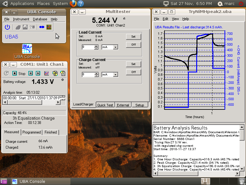
Once you have the calibration file modified, run UBA Console. Open a Multitester and select the “External Load” tab. You can choose the external load device and control to use. You can then turn them on or off. Once you are confident that your setup is working you can try a battery test.
Go to “File|Battery Analysis Routine Designer” and start a new battery analysis routine. In the load action click on the “External” tab. Choose “Primary” for both the External load device and control. Save the BAR and setup a battery analysis. Before you start the battery test select the “External Load” tab and under “Primary external load device” select the load device you want to use and under “Primary external load control” select the load control. Start the battery test.
Improvements
We can make an improvement to the constant current load. The problem is that if the battery voltage drops below 1.9V the load current will drop, but UBA Console won’t know this. The solution is to specify how much current the load draws at different voltages. We measured this and found out that below 1.5V the load current is almost 0 and above 1.9V the load current is constant. We can specify this on the ExtLoadDevice line as follows:
*ExtLoadDevice: name model aichan limit control Iin0 Vout0 I1 V1 I2 V2 I3 V3
ExtLoadDevice: My600mACC 2 -3 1 My600mASW 0 0 0 1.5 0.618 1.9 0.618 2.0
The aichan value of “-3” means that UBA Console is to use the battery voltage to determine the load current based on Current/Voltage pairs.
Let’s look at each Current/Voltage pair:
0 0 0 1.5 means that at 0V the current is zero and at 1.5V the current is also 0.
0 1.5 0.618 1.9 means that at 1.5V the current is 0 and at 1.9V the current is 618mA. Values between 1.5V and 1.9V are extrapolated.
0.618 1.9 0.618 2.0 means that at 1.9V and at 2.0V the current is 618mA. UBA Console interprets this as meaning that for battery voltage equal to or greater than 1.9V the load current is 618mA.
Email us with any questions, and to let us know if you’ve built an external load.
 Windows 10 Compatible