The standard UBA5 can charge at 2A maximum per channel or 4A if you parallel both channels (or even more if you parallel channels from multiple UBA5s). You can charge at higher currents by having your UBA5 control an external power supply using its digital outputs. This application note explains how.
Circuits
The digital outputs on Acessory1 can be used to control the charge current either directly if your power supply supports that feature, or by using either of the circuits below.
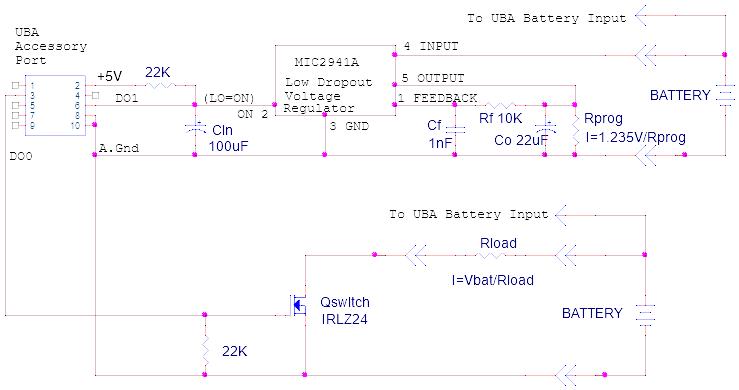
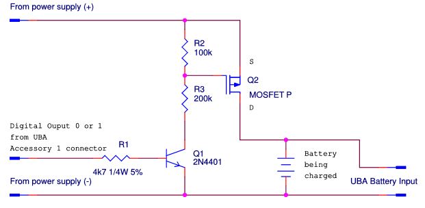
The circuit below uses a P-Channel MOSFET (or you can use a PNP bipolar transistor with appropriate resistors).
Notes:
Choose R1 and R2 such that VGS is 10 to 15V when Q1 is on.
To handle a wider variety of power supply voltages you can parallel a 15V zener diode with R2.
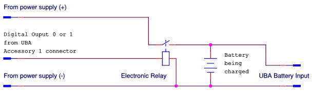
The circuit below uses an electronic relay:
Notes:
This circuit drives the electronic relay directly off of the UBA’s digital output.
If the UBA’s digital output is insufficient to control the relay, then add a drive transistor.
A mechanical relay can be used in place of the electronic relay, but a drive transistor will be required, and you will not be able to use PWM charging (explained below).
In either circuit, a “high” on the UBA digital output will connect the external power supply to the battery. Note, you must either use a power supply with a current limit or add a resistor in series to limit the charging current to a safe value for your battery. The power supply can be setup in either of two ways:
1) The output voltage can be set so that it’s the appropriate charge voltage for the battery, for example, the power supply’s voltage is set to 12.6V for a three cell lithium cell battery (3 x 4.2V).
2) The output voltage is set higher then the charge voltage of the battery. The UBA will then control the charge current by altering the duty cycle of the charging pulses (PWM). This method is better in that the UBA knows the charge current during the constant voltage phase and hence knows when the battery is fully charged.
Calibration File Modifications
To control the digital outputs, we need to add some lines to the UBA’s calibration file. Specifically an External Charge Device that specifies the charge current and an External Charge Control that specifies how the charge relay (or transistor) is controlled.
External Charge Device
The lines below describe an External Charge Device with name My3ACharger and a power supply with a 3A constant current.
*ExtChargeDevice: name model aichan do Ro limit control Iin0 Vout0 Vout0ExtChargeDevice: My3ACharger 5 -1 x 0 100 ERelay1 3 0
External Charge Control
The lines below describe an electronic relay with name ERelay1 that is controlled by digital output ‘0’ and is active high (the ‘i’ in ‘xi’).
*ExtLoadControl name model dochan maxamps
ExtChargeControl: ERelay1 2 xi ! 0
More information on using external devices for control can be found in our External Devices Manual (available on the Support page of our website).
UBA S/W:
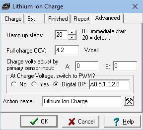
The latest version of UBA S/W (version 2.00B4 Released December, 2019) supports constant voltage charging using an external power supply and an electronic relay controlled by a digital PWM signal from the UBA.
In the charging action you would select the Digital Ou
tput option (Digital OP) as shown here:
Leave the parameter field (“A0.5,1.0,2.0”) default. More information on the parameter field can be found in the help file (click “Help” to access it).
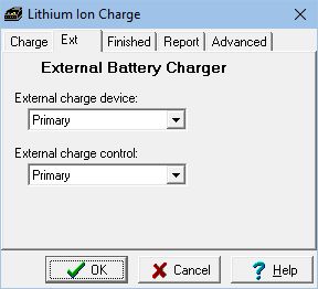
And select the External charge control and device as shown:
Then when starting the battery analysis you would select the appropriate external charge control and device as shown below:
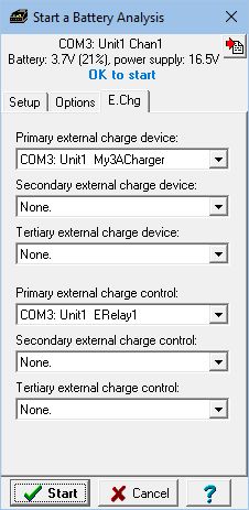
That’s it, now start the analysis.
 Windows 10 Compatible