Although small in size, the UBA5 still packs a punch with 90W of discharge power using both channels. But for some batteries, that’s not enough.
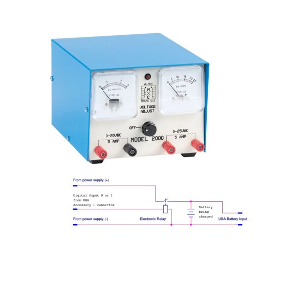
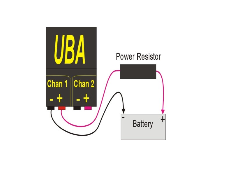
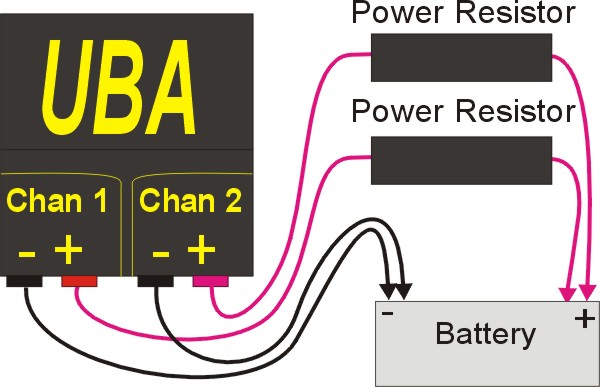
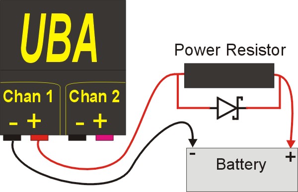
You can increase the discharge capability of the UBA5 by having it control external loads. The UBA5 has two digital outputs on its accessory port (and more on a second accessory port) that are under BAR program control and can be used to turn on or off an external electronic load or control an external relay, either electronic or mechanical. More information about using the UBA digital outputs can be found on our External Devices Manual available on the Support page of our website. We also have an application note: External Battery Discharger. But there’s another way to increase the discharge power of the UBA5, and it offers the advantage of being very simple and allowing control of the discharge current. The solution is to insert a power resistor in series with your battery as shown below:
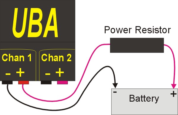
The series resistor “drops” the voltage that the UBA sees, and thus the UBA’s internal power dissipation is reduced and you can discharge your battery at a higher rate (with the maximum set by the UBA’s maximum current, not the UBA’s maximum power). The beauty of this solution is that if you tell the UBA the value of the series power resistor, it will calculate the voltage drop on the resistor and use the actual battery voltage for its report and graph. The result is that you can triple the UBA’s power handling capability for minimal cost.
This is best illustrated by a couple of examples:
Example 1:
Test a 11.1V 3S Li-Ion Battery (or a 12V SLA) at 12A or 24A
You will need our UBA5-24A battery analyzer that can discharge at up to 12A per channel with the standard UBA5 45W limit per channel for this analysis. This battery analyzer model is designed for testing single lithium cells. At a 12A load, a li-ion cell will generally supply anywhere from 3.6V to 4.1V a few seconds after the load is applied. For this example, we’ll assume that the battery supplies 3.9V at a12A load after one minute, So the UBA5 will be dissipating 46.8W which exceeds its 45W limit. The UBA5 can allow this for the two minutes while the battery voltage is dropping.
Below is the test result of testing a single cell at 12A connected directly to the UBA5-24A (series resistor not used). Notice the full 12A discharge current.
Now let’s test a 11.1V lithium ion battery at 12A. We will use a 0.7 Ohm 100W resistor in series with the battery. Now when the UBA5 sets its load to 12A, 8.4V will drop across the 0.7 Ohm resistor, and the UBA5 will see just 3.6V (using the high value of 4V per cell with the application of the 12A load). 3.6V times 12A is 43.2W, which is within the UBA5’s 45W limit. The result is that we are discharging a 11.1 3S lithium ion battery (or 12V SLA) at 12A. If we used two 0.7 ohm 100W resistors (one for each channel) we could discharge the battery at 24A with our UBA5-24A.
Procedure
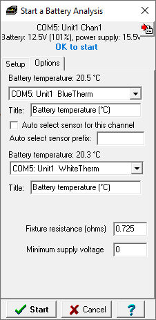
Start up the battery analysis as you normally would but on
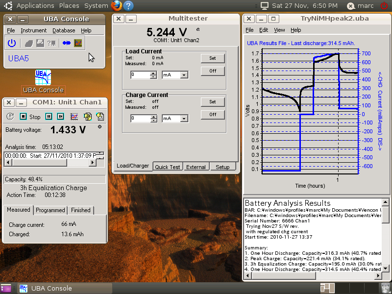
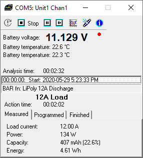
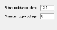
the Options tab enter the resistor value in the Fixture resistance field. In my example, I’m using a 0.7 ohm resistor and I’ve added 0.025 ohms for the wire resistance. This UBA5-24A has the Vencon optional temperature probes installed so I’ll use them to monitor the battery temperature. Below is a screen shot of the running analysis. Notice the 12A measured load current and the 134W dissipation.
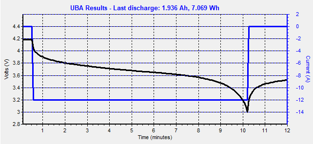
Here is the analysis result:
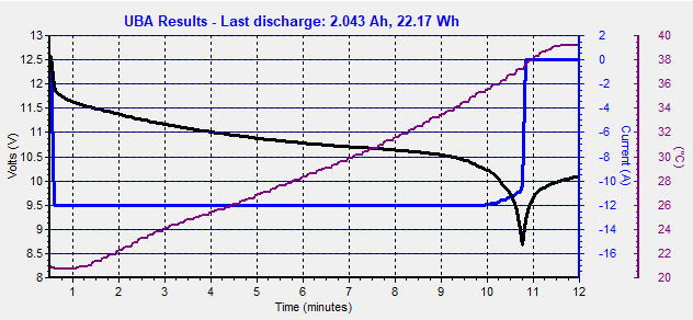
Notice how the battery is being discharged at the full 12A up until the 10 minute mark where the load current starts to decrease as the battery passes through 10V. The reason for this is that the voltage that the UBA5 sees is dropping below the minimum guaranteed battery voltage for full load. At a battery voltage of 10.2V (3.4V/cell), the UBA5 is only seeing 1.5V (10.2V – 12A x 0.725ohm). If a series resistor with slightly lower resistance or lower load current was used then you could avoid this current drop off. But if you use a series resistor that has a resistance too low, then the UBA5 will see a voltage that is too high at the beginning of the analysis and drop the load current to stay within it’s 45W limits. So there’s a balance between a series resistor that has a resistance too high or too low. But once you find the optimum resistance, you can triple the load power of your UBA5 setup for minimal cost.
Example 2:
Test a 44.4V 12S Li-Ion Battery at 2.5A
Although we make UBA5’s with extended voltage ranges, they do still retain the 45W per channel load limit which can be an issue for batteries with a capacity greater then 1Ah. The easiest solution is to simply parallel both channels, which gives you double the load current. Or we can add a power resistor in series with the battery.
For this example, I have a 2.5Ah 12S battery that I want to test at 1C (2.5A) using my UBA5-60V. This is about 125W (4.1V/cell x 12S x 2.5A) – too much for a single channel, or even for two paralleled channels.
Let’s do the math:
Maximum voltage that the UBA5 can handle at 2.5A: 45W / 2.5A = 18V.
Assume a 4.1V per cell voltage on the battery (it will start at 4.2V and quickly drop down, but not as much as the previous example as we’re just drawing 1C from the battery). So the initial battery voltage will be about 49V. Thus we need our resistor to drop 31V (49V – 18V). Calculate the resistor required using Ohms law and you get 12.4 ohms (31V / 2.5A), and 78W (31V x 2.5A).
I have a 12.5 ohm resistor, so let’s check the minimum voltage:
Assume a 2.9V/cell cutoff, so the minimum voltage will be 34.8V (12S x 2.9V/cell).
At the cutoff voltage, the UBA5 will “see” 3.5V (34.8V – 2.5A x 12.5V), which is fine.
I ran the analysis on my 12S battery.
Remember to enter the series resistor’s resistance on the Option tab when starting the analysis (the 25milliohms of wiring resistance in this example isn’t significant):
Here’s the analysis results:
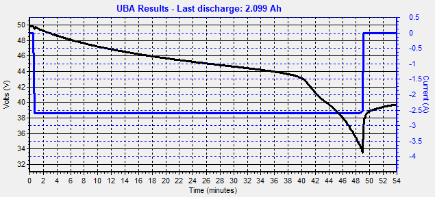
It works, our 12S 2.5Ah battery is being discharge at 1C and gives us 2.1Ah (it’s an old battery).
Notice the knee in the discharge curve at 40 minutes. This because for this test I used two 6S batteries in series and one had a slightly higher capacity then the other, so the lower capacity battery was discharged first . Also the actual load current was closer to 2.6A (I was using an uncalibrated UBA5-60V) so the final voltage that the UBA5 saw was right at its minimum which caused the slight rounding of the discharge current at cutoff.
So for a minor cost of a power resistor, you can triple the power handling capability of the UBA5-60V (same for the UBA5-44V).
Combining Channels
You can use a second series power resistor on the second channel to double the load current. In the examples above, if you used another 0.7 ohm (example 1) or 12.5 ohm (example 2) 100W on channel two, you can discharge your 12V battery at 24A (example 1) or your 12S battery at 5A (example 2). If you’re combining both channels, then enter the parallel resistance of the batter, i.e. 0.35 ohms for example 1 or 6.25 ohms for example 2.
Note: The second negative battery lead (connected to channel 2) is optional for testing at 12S (as only 5A flows through a single negative lead), but highly recommended when discharging at 24A.
Charging with a Series Resistor
The UBA software only compensates for the fixture resistance during load, not while charging. For constant current charging (NiCd/NiMH or initial phase of Li-ion/SLA charging), this has little if any effect, but it will slow down the charging a bit during the constant voltage phase. In our example above, a 2A charging current through the 0.7 ohm resistor result in a voltage drop of 1.4V, or 0.5V per cell. The UBA5 will still be able to charge your battery, it just will take longer. If you are using the UBA5 in this setup to charge your battery then you can minimize the voltage drop during charging by adding a Schottky diode in parallel with the series resistor. This will the voltage drop will only be about 100mV per cell (example 1) or 30mV per cell (example 2).
 Windows 10 Compatible